1625-2 / 1625-2-KIT GEO Earth Ground Tester
Most complete earth ground tester that can perform four types of earth ground measurements
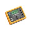
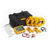
The Fluke 1625-2 GEO Earth Ground Tester Kit offers you simpler and faster earth ground tests than ever before. The 1625-2 offers internal memory storage up to 1500 records, accessible via USB port for rapid data transfer and viewing of results. This earth ground tester also gives you world-class accessories that take the tedium out of earth ground testing. New wire reels speed up setup and tear down time as much as 50%. Heavy duty stakes can be hammered into dry, hard soil. And new color-coded wires make setup simple and help eliminate mistakes.
The 1625-5 improves your earth ground processing with automatic frequency control (AFC), R* measurement, adjustable limits, 3- and 4- pole fall-of-potential earth resistance loop testing, and 4-pole soil resistivity testing. It also offers selective earth ground rod testing using 1 clamp and stakeless earth ground rod testing using 2 clamps. It is IP56 rated for outdoor use and comes with a rugged carrying case.
Kit includes the GEO Earth Ground Tester, 2 clamps, C1620 professional carrying case, 4 earth ground stakes, and 3 cable reels.
• Measures earth group loop resistances using only clamps (does not require earth ground stakes)
• Automatic Frequency Control (AFC) - identifies existing interference and chooses a measurement frequency to minimize its effect, providing more accurate earth ground value
• R* measurement - calculates earth ground impedance at 55 Hz to more accurately reflect the earth ground resistance that a fault-to earth ground would see
• Adjustable limits - for quicker testing
• 3- and 4-pole Fall-of-Potential, earth resistance loop testing
• 4-pole Soil Resistivity testing
• Selective earth ground rod testing using 1 clamp
• Stakeless earth ground rod testing using 2 clamps
• IP56 rated for outdoor use
• Rugged carrying case
• USB data storage and transfer

Accessories
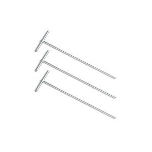
![ES 162 P3 2 3 Pole Stake Kit 03276]() Fluke
FlukeES-162P3-2 3 Pole Stake Kit
Stakes and 2 wire reels (25 and 50m) for fall-of-potential testing
Buy now!$631.39 CADNormally ships in 1-2 weeks Fluke
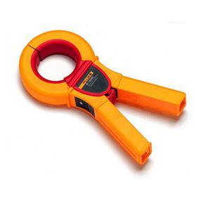
FlukeEI-162BN 320 mm Diameter Split Core Transformer
Used as a selective clamp for ground loop resistance measurement around power pylons
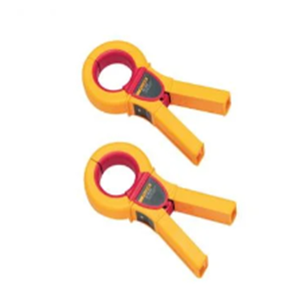
Buy now!$5,665.79 CADNormally ships in 4-6 weeks![EI 1623 Selective Stakeless Clamp Set 03353]() Fluke
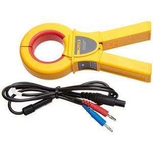
FlukeEI-1623 Selective/Stakeless Clamp Set
Used along with the Fluke 1623-2 and 1625-2 to perform Selective and Stakeless testing
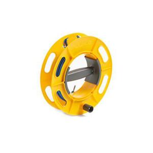
Buy now!$1,546.99 CADNormally ships in 4-6 weeks![CABLE REEL Ground Earth Cable Reel 03449]() Fluke
FlukeCABLE-REEL Ground/Earth Cable Reel
Ground/earth cable reel in 25 m or 50 m
Starting at$166.59 CADNormally ships in 4-6 weeks![EI 162 AC Clip on Current Transformer Inducting 03452]() Fluke
FlukeEI-162AC Clip-on Current Transformer (Inducting)
Inducing clip-on current transformer for the 1623-2 / 1625-2 earth ground testers and kits
Buy now!$1,026.19 CADNormally ships in 4-6 weeks![EI 162 X Clip on Current Transformer Sensing with Shielded Cable Set 03453]() Fluke
FlukeEI-162X Clip-on Current Transformer (Sensing) with Shielded Cable Set
Sensing clip-on current transformer with shielded cable set for the 1623-2 / 1625-2 earth ground testers and kits
Buy now!$1,350.99 CADNormally ships in 4-6 weeks