Starting at $833.51CAD
ConfigureFluke
FEV100 Electric Vehicle Charging Station EVSE test adap.
Test the safety and performance of a type 1, level 1 or level 2 electric vehicle ac charging stations
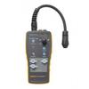


Test the safety and performance of a type 1, level 1 or level 2 electric vehicle ac charging stations (EVSEs) with the Fluke FEV100. This test adapter simulates the presence of an electrical vehicle, allowing you to conduct tests in combination with appropriate test instruments such as a digital multimeter or oscilloscope. Use the FEV100 to verify an EVSE is working properly after install and during periodic maintenance, or troubleshoot an EVSE if it is not delivering the appropriate charge.
Electrical safety
EVSE charging cables may become damaged over the course of use, increasing electric shock risks to users. Stay protected from and check risk of electric shock with the GFCI trip test. This function verifies the breaker of the EVSE is connected by detecting ground faults. Additionally, the PE grounding protection pre-test verifies that there is no presence of dangerous voltage at the ground terminal.
Simplicity and convenience
Perform a variety of tests including ground fault checks, insulation of wires, measuring voltage and duty cycle to see max current available for charging all in one adapter that safely integrates with the Fluke portfolio of test and measurement tools. There is no need to bring an electric vehicle onsite for EVSE troubleshooting: the adapter acts as an electric vehicle when connected to an EVSE for easy performance and maintenance testing.
• Check protective earth for correct wiring and functioning with the PE pre-test feature.
• Perform GFCI troubleshooting of EVSE and verify operation within safety standards.
• Test charging states of EVSE with CP state simulation.
• Verify charging voltage and maximum available current using a multimeter.
• SAE J1772 compliant to North American standards.
Request a Calibration Quote
We’re here to make calibration easy. Request a quote today and let our team give you the care, precision, and service you can trust.
Learn moreBrowse By Brands
Uncover the brands that set the standard for quality and dependability in every industry we serve.
Learn more