Starting at $978.00CAD
ConfigurePrecision Digital
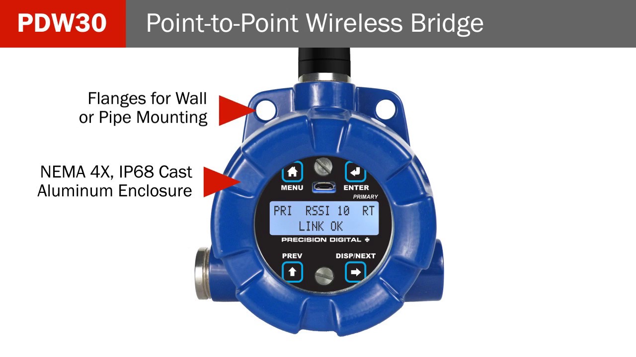
PDW90 Point to Mulit-Point Wireless System
Consists of field units (up to 32) that accept 4-20 mA signals and transmits them wirelessly to a base station
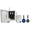
In its most basic form, the PDW90 consists of field units (up to 32) that accept 4-20 mA signals and transmits them wirelessly to a base station. The primary advantage of this system is how simple and economical it is to get multiple signals (not just 4-20 mA, also discrete (digital) and Modbus) from where you have them to where you need them – all without having to run wires!
The wireless communication between the field units and the base station is bi-directional. That means you can send 4-20 mA, discrete and Modbus signals from the field units to the base station and also send completely different 4-20 mA, discrete and Modbus signals from the base station to the field units. For instance, the field unit could send a 4-20 mA signal to the base station corresponding to the level in a tank and the base station could send a 4-20 mA sig-nal to the field unit to control a valve.
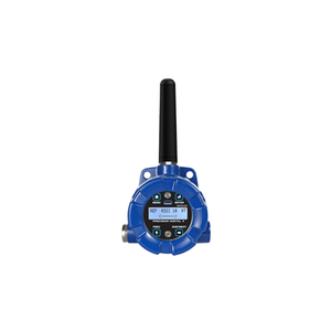
Field units are also equipped with four digital I/O that can each be independently programmed as an input or an output. A Loss of Signal warning is also available by connecting devices to the G and LS screw terminals.
To indicate alarm situations in the field, the field unit can be equipped with an optional, field installable, two relays module. These relays are rated Form A (SPST) 5A and are controlled by the digital outputs on the base station.
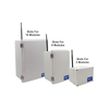
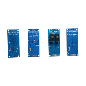
The base stations are available in configurations for 2, 6, or 16 I/O slots for a variety of field installable I/O modules. The available I/O modules are:
Dual Analog Input
Dual Analog Output
Dual Relay Output
Four Digital I/O
The specified range between the base station and field units is 1 mile line-of-sight outdoor and 500 feet indoor and repeaters are available to extend the range. A low-cost wireless survey tool, Model PDA10, is available to test the signal strength of your application before you buy.
• Signal Wire Replacement System Consisting of Wireless Base Station and Field Units
• Wireless Point to Multi-Point Signal Wire Replacement for up to 32 4-20 mA Signals
• Range: 1 Mile Line-of-Sight Outdoor, 500 Feet Indoor; Repeaters Available to Extend Range
• Wireless Transmission Between Base Station and any Field Unit of
◦ 4-20 mA (Separate Signals to and from Base Station))
◦ Discrete (4 digital I/O Signals to and from Base Station))
◦ RS-485 Modbus
• Inputs: (Wired to Field Units) 4-20 mA or 0-10 V (1), Discrete/Digital (up to 4), Modbus
• Outputs: (Wired to Field Units) 4-20 mA (1), Discrete/Digital (up to 4), Relays (2, opt), Modbus
• Base Station I/O Modules for 4-20 mA Inputs, 4-20 mA Outputs, Relay Outputs, Digital I/O
• Base Stations with slots for 2, 6, or 16 Field Installable I/O Modules and Modbus
• Loss of Signal (LoS) Digital Output
• PDA10 Signal Strength Survey Tool to "Try Before You Buy"
• Simple to Configure Using PDW Manager Programming Software and On-Board USB
• Device Communication Secured by Enabling 128-bit AES Encryption
• Password Protection
• Remote Yagi Directional Antennas Available
• Base Stations Housed in Plastic NEMA 4X Field Enclosures
• Field Units Available in IP68, NEMA 4X Aluminum & Stainless Steel Enclosures
• Field Unit Operating Temperature Range: -55 to 75°C (-67 to 167°F)
• PCBs are Conformal Coated for Dust & Humidity Protection
• Power: 9-30 VDC, Base Station & Field Units
• 3-Year Warranty
![PDA10 Wireless Survey Toolkit 00808]() Precision Digital
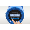
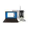
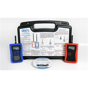
Precision DigitalPDA10 Wireless Survey Toolkit
Intended to be used in conjunction with PDW30 or PDW90 wireless products, comes with a handheld unit and a target unit
Buy now!$1,160.00 CADNormally ships in 1-2 weeks![PDW30 RNA Wireless Repeater 05369]() Precision Digital
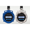
Precision DigitalPDW30-RNA Wireless Repeater
Retransmits wireless signals, broadcasts long distances and around obstacles
This product is no longer available. Contact us at 800-567-8686 for alternative solutions.![PDW90 Base Station Module 05370]() Precision Digital
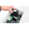
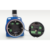
Precision DigitalPDW90 Base Station Module
Modules are easy to install and add functionality to the wireless system
This product is no longer available. Contact us at 800-567-8686 for alternative solutions.![PDA3100 Antenna Extension Cable 05371]() Precision Digital
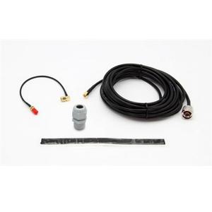
Precision DigitalPDA3100 Antenna Extension Cable
Antenna extension cable for PDW wireless products
This product is no longer available. Contact us at 800-567-8686 for alternative solutions. Precision Digital
PDA3900 Yagi Directional Antenna
Yagi directional antemma for PDW wireless productst
This product is no longer available. Contact us at 800-567-8686 for alternative solutions.![PDA3900 12 Standard Antenna 05373]() Precision Digital
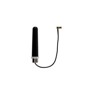
Precision DigitalPDA3900-12 Standard Antenna
Standard antenna for the PDW wireless products
This product is no longer available. Contact us at 800-567-8686 for alternative solutions.![PDA6963 SS Pipe Mounting Kits 05374]() Precision Digital
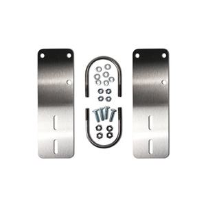
Precision DigitalPDA6963 SS Pipe Mounting Kits
Two stainless steel pipe mounting kits for PDW90 wireless field units or PDW30 primary and secondary units
This product is no longer available. Contact us at 800-567-8686 for alternative solutions.
Request a Calibration Quote
We’re here to make calibration easy. Request a quote today and let our team give you the care, precision, and service you can trust.
Learn moreBrowse By Brands
Uncover the brands that set the standard for quality and dependability in every industry we serve.
Learn more